🕷️ Mini-Bug Robot
A four-legged desktop robot with no 3D-printed chassis — just servos, silicone, and duct tape holding it all together, walking under Xbox control over Bluetooth.
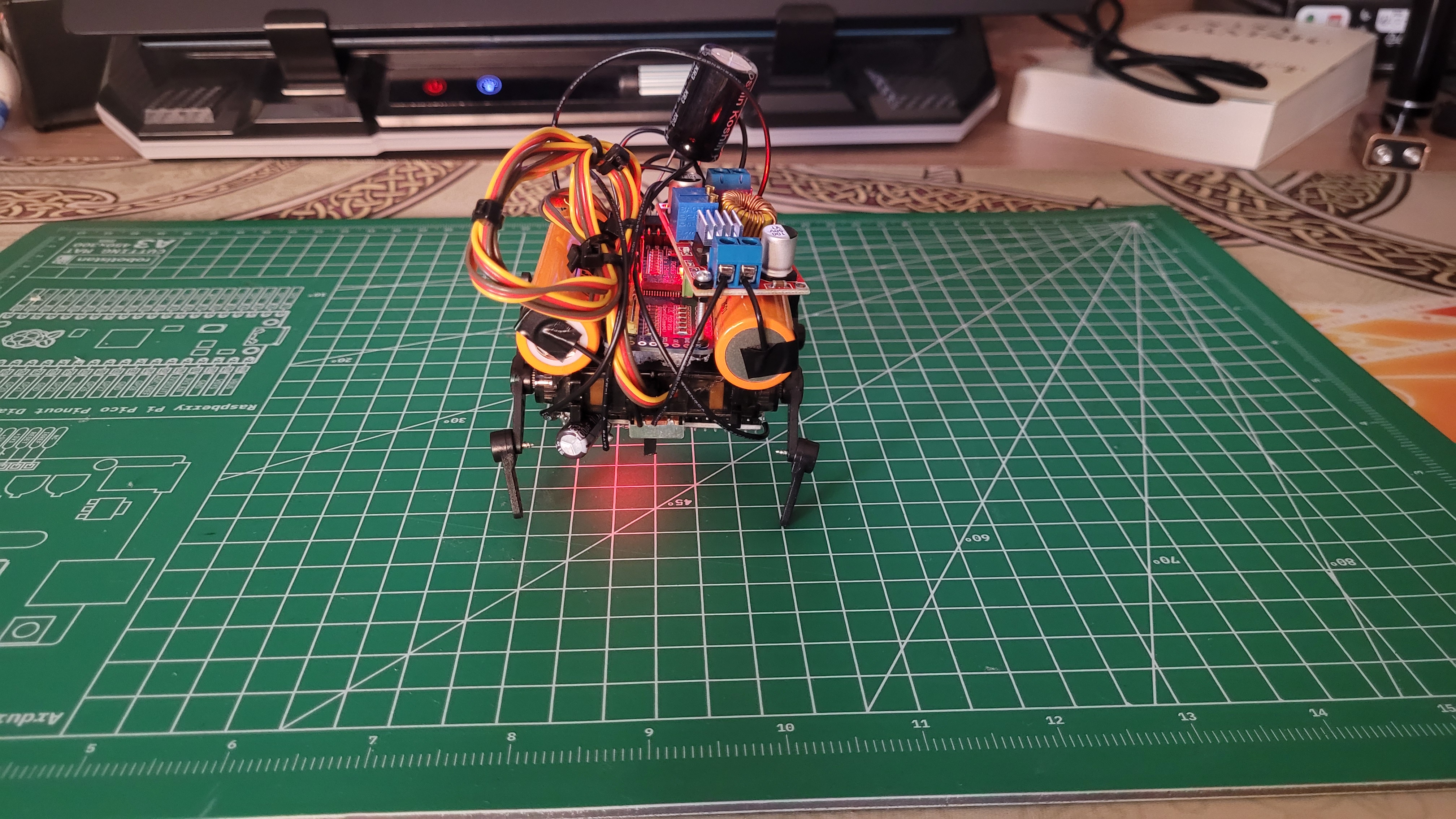
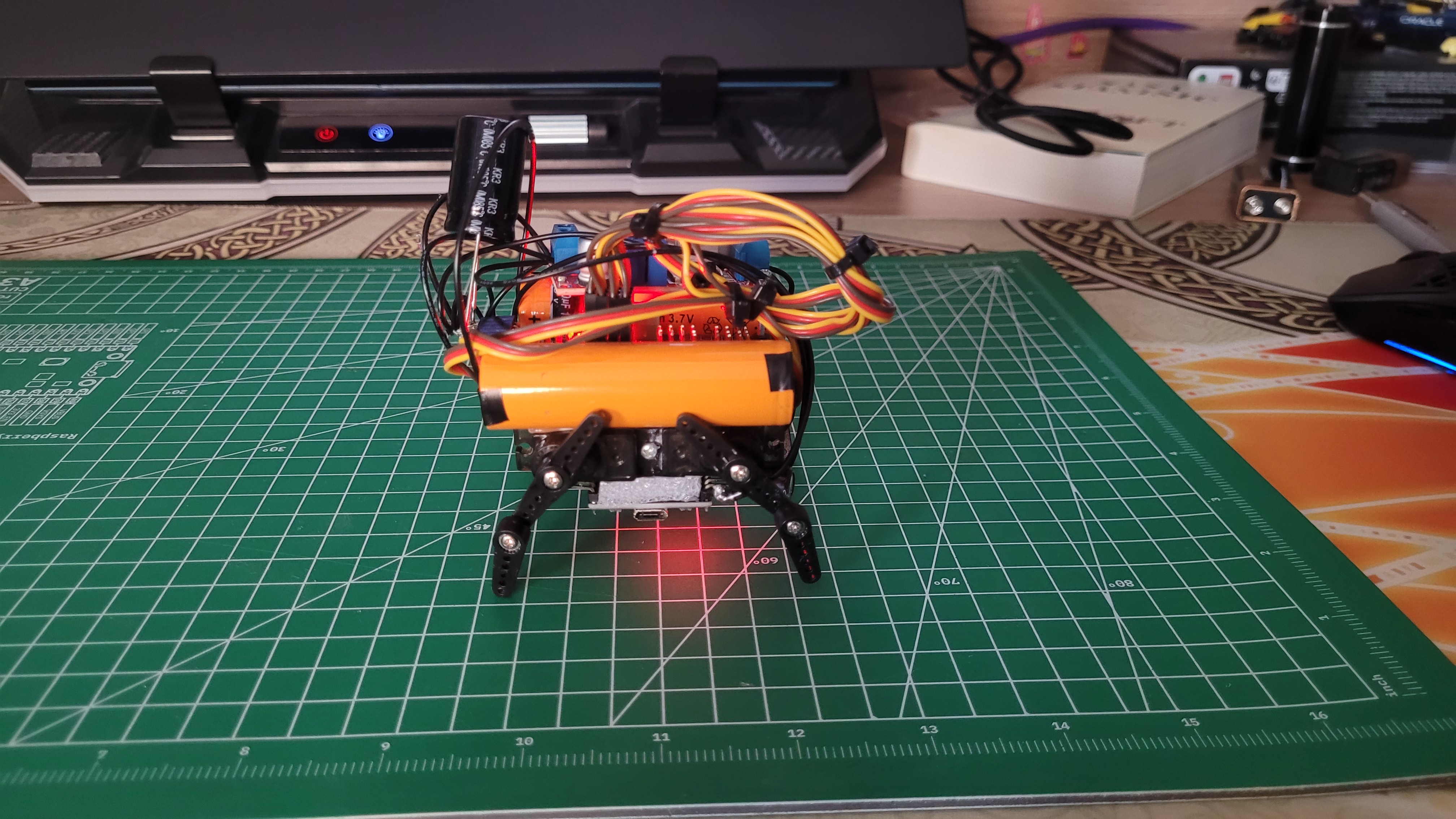
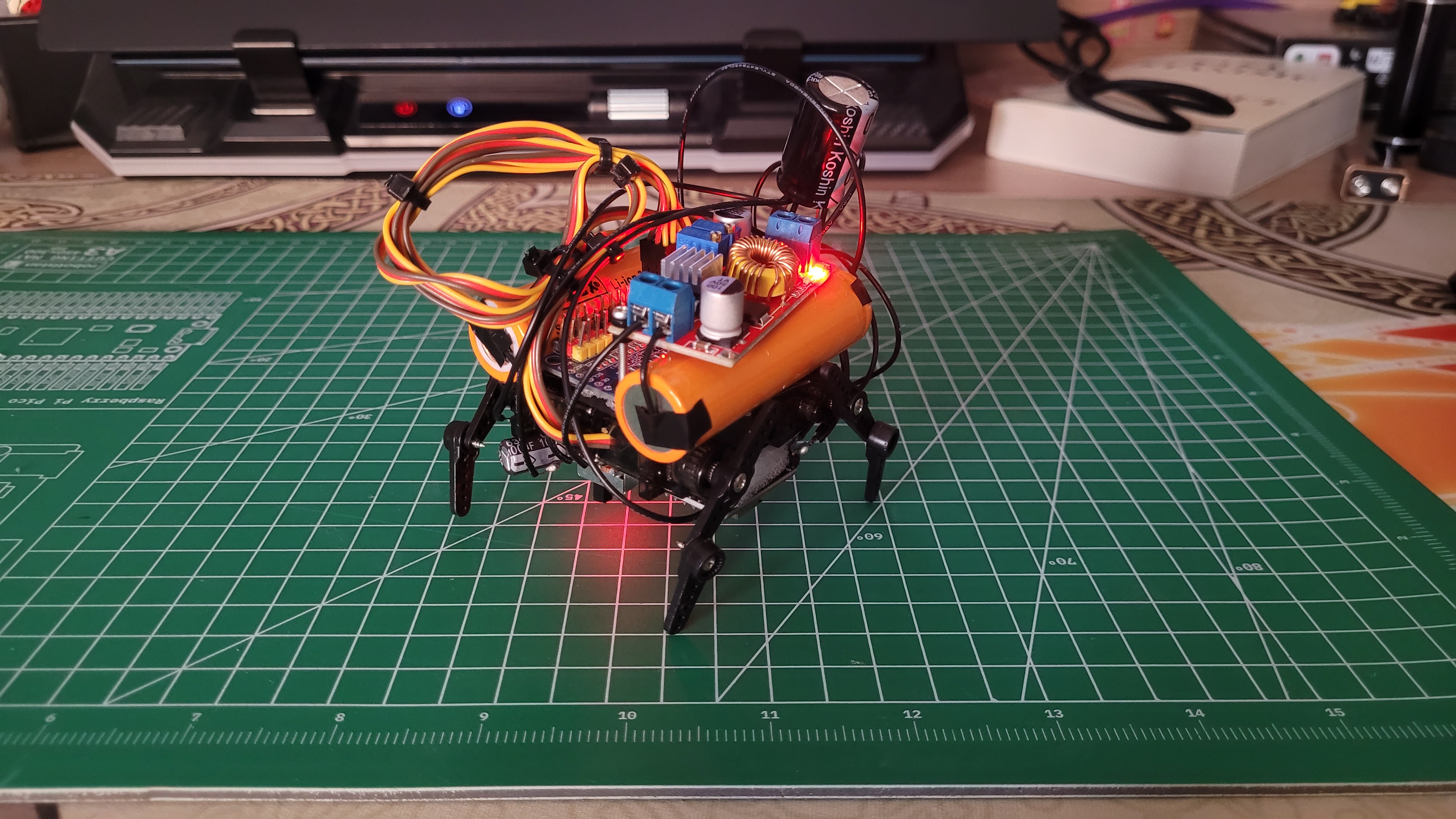
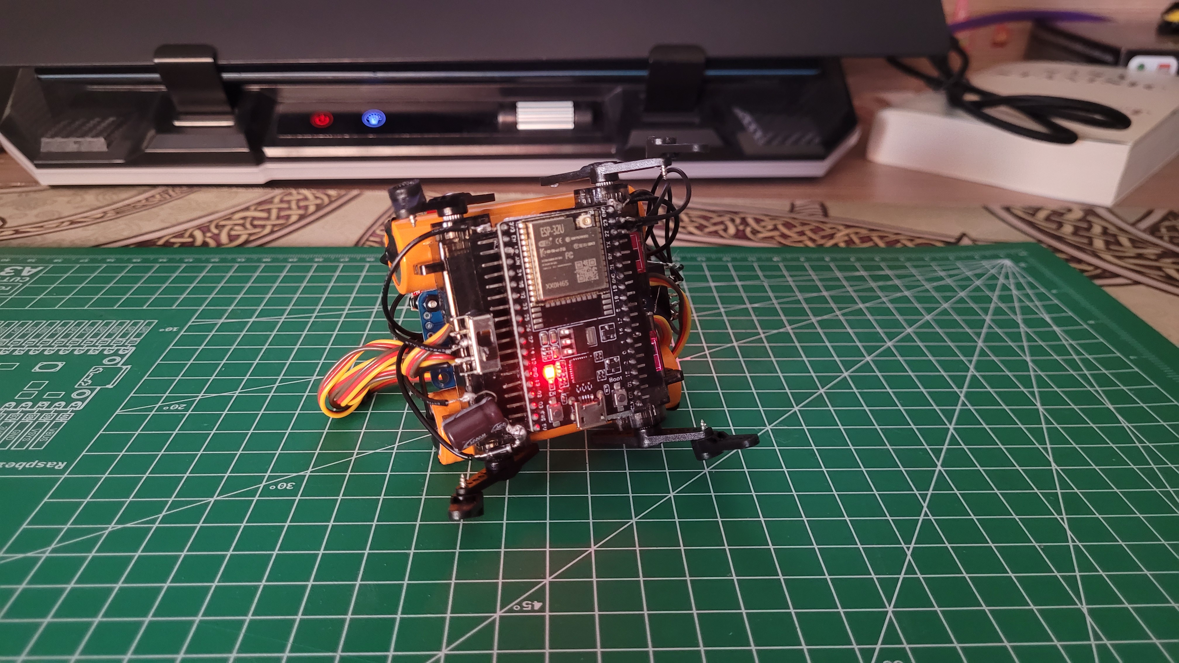
The frame isn't really a frame. Four MG90S servos are screwed directly to each other and reinforced with silicone and duct tape — there's no printed body underneath. Each leg gets a servo horn plus a matching plastic attachment that extends and curves it into an actual leg shape, 8 horns in total.
The electronics stack on top of that: an ESP32-WROOM-32U siliconed underneath the body, a PCA9685 PWM driver siliconed above it, and an XL4015 buck converter siliconed on top of that. Two Li-ion cells sit on either side of the driver board, wired in series for 7.4V. A 1N4001 diode now sits in series on the 5V line for reverse-polarity protection, and a 100µF capacitor bridges the ESP32's 5V and GND legs to smooth its supply.
⚡ Circuit
Two Li-ion cells in series (7.4V) feed an XL4015 buck converter set to output 5V, which powers both the ESP32 and the PCA9685's servo rail. A 1N4001 diode sits in series on the branch feeding the ESP32's 5V pin for reverse-polarity protection, and a 100µF capacitor bridges the ESP32's 5V and GND pins to smooth its supply. The PCA9685 gets its logic power from the ESP32's 3.3V line and talks over I2C — GPIO22 to SDA, GPIO23 to SCL. All four servos run off PCA9685 channels 4 through 7, with a 3300µF capacitor in parallel on the power rail to smooth out the current draw when every servo moves at once.
🎮 Control Scheme
Movement is driven by an Xbox controller paired over Bluetooth. The main loop checks button and trigger state every frame and calls the matching motion function — each one just moves the "right" or "left" pair of servos in a set pattern.
| Input | Action |
|---|---|
| RT | Right-side servos step forward |
| LT | Left-side servos step forward |
| RB | Right-side servos step backward |
| LB | Left-side servos step backward |
| A | Forward walk (RT + LT combined) |
| B | Backward walk (RB + LB combined) |
| X | Reset to default stance (90°) |
| Y | Lying position |
| D-Pad ↑ | Dance |
| D-Pad ↓ | Stand on rear legs |
To come back down from the rear-leg stand: press Y (lying), then X (default).
View Full Firmware on GitHub